Tension & Tensile Membrane Structure Design
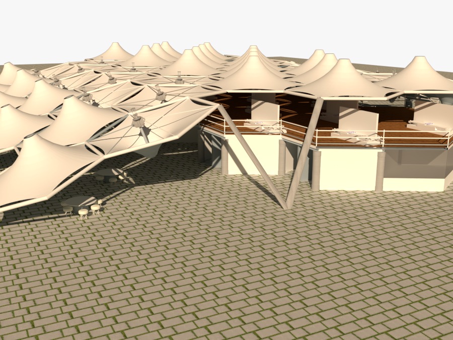
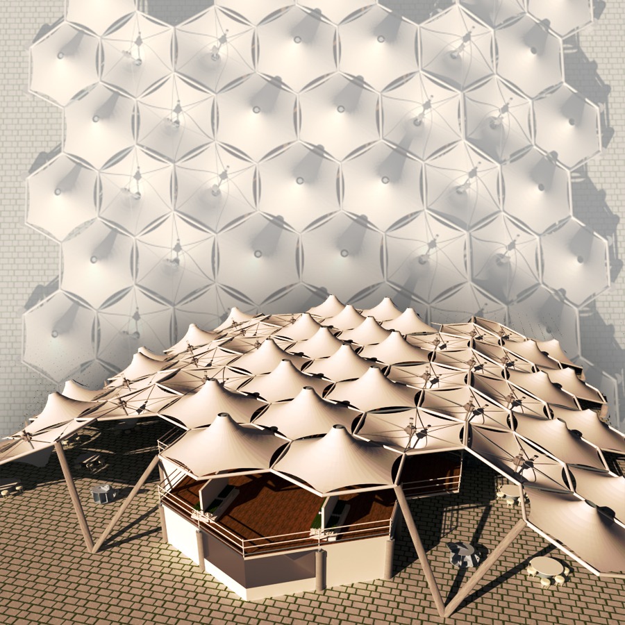
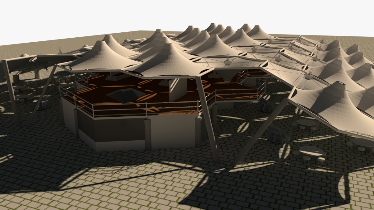
Tensile membrane structures represent a captivating blend of architectural innovation and structural ingenuity. These lightweight, elegant structures are characterized by their ability to span vast distances with minimal material, creating awe-inspiring spaces that seamlessly integrate with their surroundings. Neesaun Zarbakhat leverages BIM and advanced 3D modeling to deliver cutting-edge architectural renderings that help clients visualize how our tension membrane structures fulfill their needs. Our team of industrial designers and architects, skilled in form, function, and aesthetics, creates realistic 3D visualizations that bridge the gap between concept and construction.


How It Works
The architect’s initial sketches & visualizations lay the groundwork, considering the functional needs of the structure and its intended visual impact also serve as the foundation for engineering analysis. Using these sketches, 3D model, a specialist engineer creates a preliminary design, preliminary FEA and wind load studies incorporating both the necessary geometric shape and essential structural elements like supports, bracing, and anchorages. This draft allows for a budget estimate. Finally, the architect, client, and engineer collaborate to review this design, ensuring the final aesthetic, functionality, budget align, Ensuring structural stability, proper membrane shaping, and stress optimization.
Key Principles of Tensile Membrane Structure Design
Form Follows Force: The design of tensile membrane structures is intrinsically linked to the forces they experience. The membrane’s shape is a direct response to the interplay of tension, compression, and other structural forces, resulting in organic and graceful forms.
Minimal Material, Maximum Impact: Tensile membranes are incredibly lightweight, requiring less material than traditional construction methods. This not only reduces costs and environmental impact but also allows for greater design flexibility and the creation of striking, column-free spaces.
Light and Transparency: Tensile membranes often offer varying degrees of translucency, allowing natural light to flood interior spaces. This creates a sense of openness and connection to the outdoors while also reducing the need for artificial lighting.
Durability and Longevity: Modern tensile membranes are engineered to withstand harsh weather conditions and UV radiation, ensuring their longevity and minimal maintenance requirements.
Design Considerations
Concept
Begin by choosing the fundamental shape of your desired structure, considering options like a Cone, Barrel Vault, Folded Plate, Hyperbolic Paraboloid (Hy-Par), or a unique combination. Keep in mind that a membrane under uniform stress naturally forms a shape within its given boundaries.
Boundary Conditions
- Will you incorporate edge cables (catenary cables), ridge/valley cables, or radial cables?
- Will the membrane be clamped solely to a rigid steel perimeter?
- Will there be posts supported by guyed cables, or will they have moment connections at their base?
- If using a cone-shaped fabric, will the mast be anchored to the ground or suspended by cables (a “flying mast”)?
- If using a mast, will it be tilted or vertical?
Answering these questions will establish clear boundary conditions for your design.
Form Finding
If you primarily need to determine the fabric’s shape, calculate your defined boundary conditions and fabric mesh into suitable form-finding formulas to generate the desired form. It’s critical to avoid “flat” areas in the fabric, as these will struggle to handle loads effectively. Remember, the membrane supports loads by deflecting and transferring tension back to its perimeter. Consequently, the perimeter must be adequately robust to manage these tension loads, often necessitating a compression ring, frame, or tie-backs in areas without a continuous ring or frame. Additionally, ensure that the design avoids horizontal or near-horizontal sections where rain or snow could accumulate and cause ponding.
Static Analysis
The membrane’s statics dictate the overall detailed design, defining edge geometry and load transfer points. As membrane structures deform under loads like wind and snow, connections to the supporting structure, existing buildings, or foundations must accommodate this movement, a comprehensive Finite Element Method (FEM) model needs to be constructed, incorporating material and section properties. The static calculation, based on the form-finding data, involves extensive analysis. This includes accounting for various load cases, the three-dimensional nature of the roof, and the biaxial expansion behavior of the membrane material.
Pre-stress and Dead Load: The initial tension in the membrane and the weight of the structure itself
Live Load: Loads that can change over time, like snow, rain, or occupancy
Wind Load: Wind pressure from various directions, especially if the structure lacks symmetry. The minimal material weight (around 1-1.5 kg/m²) makes membrane structures sensitive to wind loads. While this is offset by the static equilibrium achieved through shaping and pre-stressing, it places unique demands on the supporting structure and foundations regarding load application
Thermal Load: Expansion or contraction due to temperature changes
Seismic Load: Forces resulting from earthquakes, if applicable
Stability Check: Ensuring the structure can withstand various loads without buckling or collapsing. subsoil bearing capacity rarely dictates foundation design. Depending on soil conditions, tensile loads can be managed using heavy-duty foundations or specialized ground anchors.
The potential for water accumulation or ponding on the membrane must also be evaluated. When choosing membrane strength, a substantial safety factor (typically 5) should be applied.
Material Adjustments
Secondary steel: May need to be shop-welded to primary steel to facilitate perimeter clamping.
Cable congestion: Areas with multiple converging cables might require adjustments to accommodate ear plates and cable terminations.
Membrane cut-outs: Corners of the membrane might need to be cut to accommodate structural elements; these cut-outs may necessitate reinforcement or specific edge treatments.
Field penetrations: Although ideally avoided, membrane penetrations might be necessary. These require detailed design with clamping, reinforcement, or other measures to ensure load-bearing capacity, manage deflections, and maintain water-tightness.
The detailed design phase bridges the gap between analysis and construction, ensuring that the envisioned structure can be translated into a practical and buildable reality.
Cutting Patterns
Warp & Weft: The direction along the fabric roll’s length. This affects strength and usage.
Seam Layout: Determined by warp direction, roll width, aesthetics, fabric usage, and shape. If the calculations can’t flatten a design within an acceptable error margin, more seams may be needed.
Waste Reduction: Patterning should aim to minimize fabric waste, if aesthetically possible. Triangular and trapezoidal patterns near full width nest better than long triangles, hourglass shapes, or rectangular panels over half-width but less than full width.
Fabric Properties: Understand fabric properties before creating templates. Some projects use stretchy fabric with less concern for pre-stress distribution, while others need uniform pre-stress with stiff fabrics.
Biaxial tests determine compensation—the amount templates are cut smaller to achieve desired pre-stress and geometry when stretched during installation. Most patterning techniques allow for compensation input to generate accurate cut lines.
Safety, Security & Maintenance
Tensioned membrane structures experience significantly more deflection than traditional structures. Therefore, careful consideration is necessary when placing architectural or functional elements like lighting, curtain walls, HVAC, and lightning protection to prevent contact and potential puncture of the membrane.
Furthermore, tensioned membranes are susceptible to tearing. It’s crucial to acknowledge the possibility of damage from foreign objects during the structure’s lifespan. Factors like Safety Factor and a clear Repair Procedure must be incorporated into the design. A fundamental rule is to never rely solely on the membrane to support steel elements. For example, a mast should have additional support from radial or guy cables to handle its load even if the membrane is compromised.
For maintenance, repairs, and other activities, it’s wise to include lifelines or tie-off points in the design. This ensures the safety of construction and service personnel accessing the membrane.
If the membrane surface is too large to manage as a single piece, sectionalizing with clamped field joints may be necessary.

